
NewVersion 1.1
AC Circuits, Resonance & Transformers
Drive resistors, capacitors and coils with a sine wave, watch the current lead or lag on a scope and as phasors, sweep through resonance, and see why power lines run at high voltage.
About this simulation
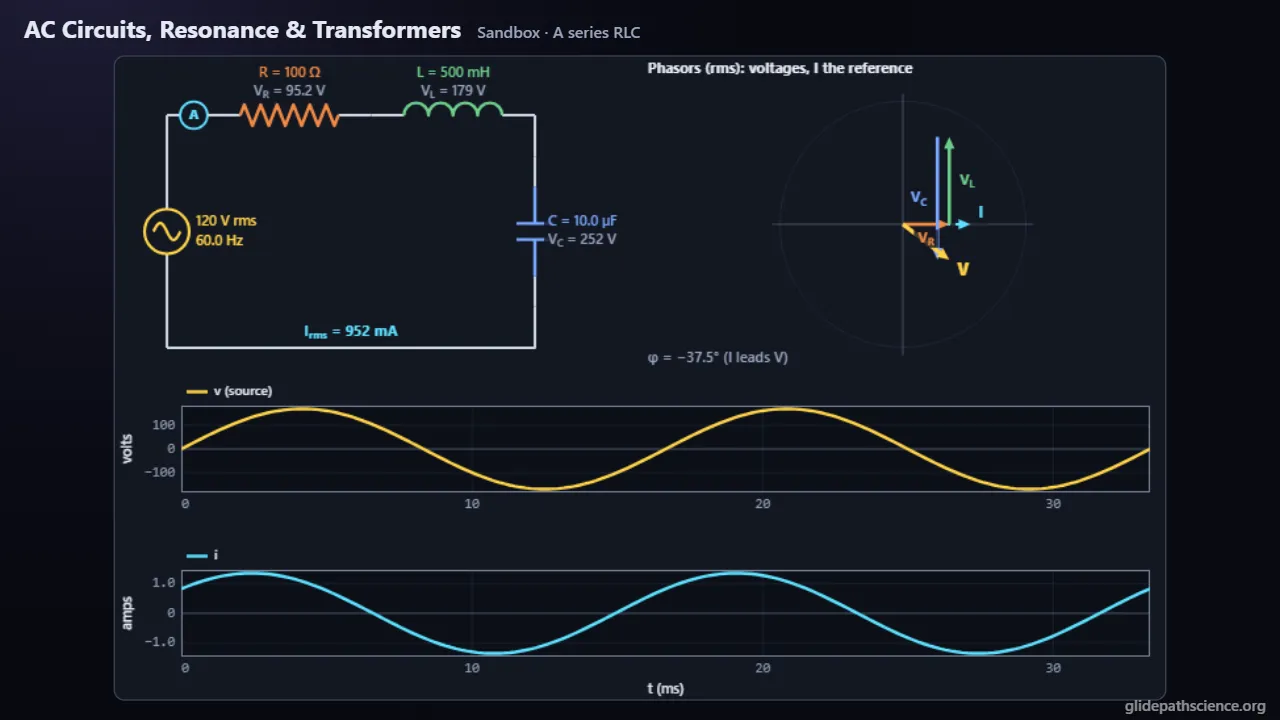
Why does a capacitor’s current lead its voltage, and why do power lines run at hundreds of kilovolts? Students put a resistor, a coil and a capacitor in series or parallel on a sine source from 1 Hz to 10 MHz and read meters, turning phasors and a two-channel scope. A guided walkthrough at two levels runs from RMS values through each part on AC, phasors, impedance and the phase angle, power and power factor and a frequency sweep to resonance, Q and the transformer; the Advanced track adds complex impedance, the switch-on transient, the parallel tank, complex power, the real transformer and three-phase power. A Phasor Bench has students drag each arrow of a phasor diagram into place and check it against the circuit; a Resonance Lab sweeps a series RLC circuit to read f₀, the half-power points and Q, beside the driven mass on a spring that matches it; and a Transmission Line steps up a plant’s voltage to send power to a town and charts the loss. Concept challenges and a prediction lab with Tune the radio round it out.
What you'll learn
- Explain that an AC meter reads rms values, V₀/√2 for a sine, and that a resistor’s current is in step with its voltage while a capacitor’s leads by 90° and a coil’s lags by 90°.
- Use X_C = 1/ωC, which falls with frequency, and X_L = ωL, which rises, and add phasors as arrows to find a series circuit’s impedance, Z = √(R² + (X_L − X_C)²).
- Find the resonant frequency, ω₀ = 1/√(LC), where the reactances cancel and only R limits the current, and explain why a smaller R gives a taller, sharper peak with a higher Q.
- Explain why only resistance takes average power, P = IV cos φ, and how a transformer trades voltage for current, V_s/V_p = N_s/N_p, so high-voltage lines lose far less.
What you can do
- Guided walkthroughStep-by-step, in Intro and Advanced tracks.
- SandboxEvery control of the model, to explore freely.
- Virtual labA realistic experiment with measurement noise and data analysis.
- Concept checksQuestions about ideas and vocabulary, with no calculating.
- PredictionCommit to a prediction, then see the result.
- Classroom demoProjector mode and recordable clips for slides.
- Works offlineA single downloadable file, verified to run without a network.
Before you start
- Resistors, capacitors and inductors in DC circuits
- Sine and cosine functions, phase and angular frequency
- For the Advanced track: complex numbers and second-order linear differential equations
Run or download
Run it in your browser
Nothing to install and no account. Works on laptops, Chromebooks, tablets, and phones.
Launch AC Circuits, Resonance & TransformersDownload for offline use
One HTML file (739 kB) that opens in any modern browser with no network: for rooms with unreliable Wi-Fi, or to keep a copy.
Download the fileFile details and checksum
- File
ac-circuits-transformers-v1.1.html- Version
- 1.1, released November 15, 2026
- Build
e08bdcc- Size
- 756,710 bytes
- SHA-256
4ccaec74b8ecef683f3a2bd8003e792ce83c93357a4023b7b9078d38d27024da- Offline
- Checked to run with all network access blocked.
The model and its limits
What the model assumes
- The steady state is computed by rms phasors at the source’s frequency, and every readout, trace and arrow comes from them.
- The switch-on transient (Advanced) is the exact solution of the driven series RLC circuit from rest: the steady state plus a decaying free oscillation.
- Ideal parts have no resistance of their own; when nothing limits a series current, the Sandbox says so and shows infinity rather than a huge number.
- The real transformer uses illustrative values for a small 120 V to 12 V, 100 VA unit: its inductance, coupling, winding resistances and a core-loss resistance.
- The transmission line is a resistance in each conductor, the town draws its power at unity power factor, and three-phase power is balanced.
What it leaves out
- Only sine waves: the V₀/√2 rule and the phasor method do not apply to other waveforms.
- No core saturation or hysteresis, eddy currents only as a fixed core-loss resistance, and a coil’s own resistance and capacitance only when added as parts.
- No skin effect, no line inductance or capacitance or the waves they carry, no reactive loads on the line, and no impedance in the generator.
- RL transients and free LC oscillations are left to Inductance & LC Oscillations, and switching converters to Buck & Boost Converters.
Cite this simulation
APA 7
Meier, D. (2026). AC Circuits, Resonance & Transformers (Version 1.1) [Computer simulation]. Glidepath Science. https://glidepathscience.org/simulations/ac-circuits-transformers/
MLA 9
Meier, David. AC Circuits, Resonance & Transformers. Version 1.1, Glidepath Science, 2026, glidepathscience.org/simulations/ac-circuits-transformers/.
AIP
D. Meier, AC Circuits, Resonance & Transformers, version 1.1 (Glidepath Science, 2026), https://glidepathscience.org/simulations/ac-circuits-transformers/.
BibTeX
@misc{meier2026accircuitsresonancetransformers,
  author       = {Meier, David},
  title        = {{AC Circuits, Resonance & Transformers}},
  year         = {2026},
  publisher    = {Glidepath Science},
  version      = {1.1},
  note         = {Interactive simulation, version 1.1},
  howpublished = {\url{https://glidepathscience.org/simulations/ac-circuits-transformers/}},
  url          = {https://glidepathscience.org/simulations/ac-circuits-transformers/}
}
Credits and license
Created by Dr. David Meier, Glidepath Science.
Based on: OpenStax, University Physics Volume 2, by Samuel J. Ling, Jeff Sanny and William Moebs: Chapter 15, “Alternating-Current Circuits,” §15.1–15.6, an open textbook licensed CC BY-NC-SA 4.0 (openstax.org). The Intro track follows its order of topics (with RMS values brought forward) and its notation; the text, numbers, figures and simulations are this lab’s own. No endorsement by OpenStax or the authors is implied.
Licensed under Creative Commons Attribution-NonCommercial-ShareAlike 4.0 International (CC BY-NC-SA 4.0). You may share and adapt it for noncommercial purposes, such as teaching, with credit and under the same license. Licensing and reuse
AI tools (Claude, from Anthropic, and ChatGPT, from OpenAI) were used in developing Glidepath Science and its simulations. Dr. David Meier reviewed, edited, and modified every release version.